This is a simple one, I don't even have a fun name for it. I showed off the prototype on Arduino subreddit awhile back and have been using and modelling with this ever since. As mentioned there, I just recently learnt about something called a Space Mouse. Literally one company made it, yeah you can find some mouse that incorporate a tiny joystick on it, but that's also cost an arm. It's a niche product that hobbyist doesn't need to get it.
If you ever made a Stream Deck (like I did on the previous post), heck or even just played with a Leonardo (Pro Micro), you basically already know how to make this. All you just need to do is read the joystick and encoder values, then send those value as hotkey the hotkey of your CAD software, and you're done.
The only thing that's missing is that Fusion 360 doesn't have a hotkey for the home view. There are some people who made a screen jacking script to do that on Windows, bet I could do the same with Automator, but I'm not a fan, one of the major key of this build is making something that I can plug into another computer and use it as is.
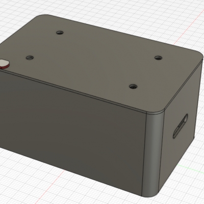
The enclosure has issue, if you can see from the cutout above, I only have space to mount the joystick from the left side, it resulted in a wonky and relatively loose joystick. Terrible to use, can't even click it. So, I just add a nub on the lid to press it down and straighten it up, worked like a charm.
However, I won't fix that issue, I'm just going to it as is because... as I write this, I am prepping for MK2. Frankly, I find that a joystick isn't a great input for 3D mouse. I tweaked it, tuned it, every way, it just doesn't feel right. So I'm exploring other input options now, a couple thing that came to mind is a trackball and that recent DIY HOTAS on YouTube. It's 100% 3D printed parts with rubber bands, hall effect sensor, and magnets. Dude is brilliant.
We as a family has lock ourselves down since around end of Feb or early March. We haven’t left the house unless it’s absolutely necessary, so the wife decided that she wanted to live-stream the game she’s playing anyway. Here’s some tips and tricks to up your live streaming game on the cheap.
1. Software
OBS, obvi! Powerful, but it’s also power hog. But free. It is not well optimized on Mac, but it's not like we're swimming with options here. On Windows you can get a certain GPU that’ll make OBS run better on it, but that’s neither here nor there.
2. Capture Card
To stream iOS game, you can actually just use a lightning cable, open QuickTime, select iPhone as source. Then use Loopback to capture the sound. On OBS, add window capture, and add the loopback as another audio source.
iShowU Audio Capture is the free alternative to Loopback, but it’s getting the whole desktop audio, if your computer dings for new messages or email, your audience will hear it too.
However, with just lightning cable, the stream lags. I think OBS just not fast enough to down scale the large iPhone screen to upload in real time. After 3 days of streaming with lightning cable, we sprung for Elgato HD60s+ (and the HDMI dongle). Completely addressed the lag complaints.
3. Stream Deck
A very simple DIY version. Super cheap, like I just need to spend $2 for the Pro Micro. I also print the re-legend-able key caps. This is my breather project while I'm building and fixing Whey. Simple, easy, just follow the guide as is. Use the exact same pins and sketch.
A couple of snags if you use it on a Mac, F14 and F15 were predefined to set brightness. And for some reason F21 and F22 doesn't trigger when I try it. So just go to Settings > Keyboard > Shortcuts > Display and unticks. Then set the shortcuts on OBS.
But I feel like I can improve things here. I have some ideas that I need to test first.
4. Key Light
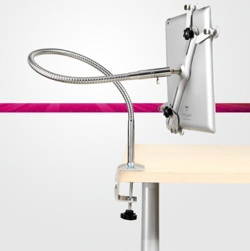
Simple project that can be done in under an hour for under $10. I just use a cardboard from Coca-Cola, don't even need to cut it, other than making a few holes for mounting and wires. And I just use an old and weak wire iPad stand clamp (something like this, but much shittier -- I bought it for like $5).
5. Green Screen
I actually just use green craft paper, kinda surprised how well it works. Mine is far messier that the one on the video. For something that cost under $2, I'm very happy with the result. Check out the hero image up top, that's the scene for Among Us, bottom left is the webcam chroma-keyed, and top right is Spotify, which brings us to my next point.
6. Spotify
A simple and beautiful little widget to show what song is currently playing on your stream. You can't use Spotify on Facebook (tested it), maybe you can get away with it on a less popular streaming service, maybe Twitch, possibly YouTube. It's just so nice to have. People stop asking what song is this. Accepting song request is a great way to start interacting with your audience.
7. Bonus
Here's what you should never do: Don't use HTML/CSS for animation. I don't know how to make animated video things, but I know HTML / CSS like the back of my hand. So, why not just make HTML animation, and add a Web Source on OBS, right?!
Nope. When we tried that, after streaming for a couple of hours the second-highest-spec 2019 16" MacBook Pro crash. The whole thing crashed. After the second time, I left activity monitor on, turns out OBS were using like 300+GB of RAM.
Maybe you can get away with it for something simple like a lower third that you turn on and off (remember to check the release source or something along that line on the Web Source properties). From there on, I've set it the "right" way, the way OBS is designed for. Scrolling text is Text Source. Simplified a lot of things.
That's it. After having done all of this, in terms of technology, you're already on par with full time streamers. The rests are on your contents and personality. gl hf.
We have a problem. Everytime anyone type in load cell arduino, it's always return HX711. I mean, it works if you don't need accuracy just a ball park figure as a trigger for other things, say like a pet feeder. If weight less than 50g, move servo to X until weight is more than 100g. Then it doesn't matter, you might feed 20g more food to your dog. However, for more interesting projects, say a smart cutting board that can weight things according to ingredients listed on your phone, then HX711 is definitely not good enough.
Enters ADS1232, while it is more expensive than HX711, it is not prohibitively so. And the datasheet is quite overwhelming for most. It is not like using HX711 where you plug one end to the load cell and the other end to the micro controller, drop in a library and BAM you've got weighs. So, let's make it like that.
Pictured on top is the simplest form of the ADS1232. On the left side, blob together CLKIN, A0, TEMP, and GND. Then bridge GND across to another GND. Bridge across 3.3V and 5V, then link GAIN0, GAIN1, SPEED, and REFP to 5V. That's it, the ADS1232 is ready to be used like HX711.
PDMN, DOUT, and SCLK connect to 3 pins on your µC.
VCC and GND out of µC are connected to both the ADS1232 and load cell excitation voltage (red and black).
Load cells signal voltage (green and white) connected to AINP1 and AINN1 on ADS1232.
On this mode, you'll need to use my simplified library for Whey. Just download and drop in the ads1232.h and ads1232.cpp onto Arduino IDE.
That's it, you can now use ADS1232 like HX711. Next let's dive a bit deeper so we can use this 24-bit analog to digital converter much better.
You'll need 4 more pins out of your µC for A0, GAIN0, GAIN1, SPEED.
SPEED pins is how you control the reading samples rate. Set it LOW for 10 samples per seconds, and HIGH for 80 samples per seconds.
Gains:
1x: GAIN0 and GAIN1 to LOW
2x: GAIN0 to HIGH, and GAIN1 to LOW
64x: GAIN0 to LOW, and GAIN1 to HIGH
128x: GAIN0 and GAIN1 to HIGH
A0 is used to read the second channel. LOW reads channel 1 (AINP1 and AINN1). HIGH reads channel 2 (AINP2 and AINN2).
IMO, these things can be decided prior to soldering things together and simplified your schema. Now that the ADS1232 has been configure, let's get some data out of it.
Power it up: set PDMN pin to LOW and SCLK to HIGH. Reverse values to power down.
Wait until new data is ready: wait until DOUT change from LOW to HIGH and back to LOW.
Next you just need to read the raw 24-bit data. Refer to the library if needed.
Once you have the raw data, it's basically done. To calibrate the scale:
Prepare a known weight, say 100g weight. But don't put it on the weight.
Reset the calibration value SCALE value to 1.
Read and store the value to OFFSET. It's to tare off your platform
Put on the known weight.
Read the value again. Now you can get the new calibration value.
SCALE = (value - OFFSET) / 100, if the known weight is 100g.
The prototype was done wrong. If you clicked through, you can see my original design. After the load cells arrived, I've spent almost 2kg of PETG to get that design to work. But it just doesn't. First, plastic flex. That design would probably work if I can laser cut aluminium (I've actually looked into a laser cutting service). But I have another problem when I mounted the OLED on the platform, when I put something heavy, the wires actually pushing the platform up making the measurement not accurate. Which made me not wanting to pursue this design any further with aluminium or other means.
On to the final design. Well, "final". I went with 2-part concept, the controller was the best I can come up with quickly, without desoldering or making any other changes to the electronics part. If you were to build this, I highly recommend you redesign this part. This has wires rat nest inside, which I believe it becomes the source of the noise (which makes it still jitters at ±0.1g). I have better stability on the original design when it worked. Which means, a better controller should be coming soon.
Build guide, codes, and STLs are available on GitHub.
Load Cell: I bought 2 from Ali, a $15 one and a $25. Neither are stable enough at 0.01g. The $25 one are more sensitive to noise. I went with the cheaper one because it is shorter, I'll have more room below the portafilter.
TTGO mini32: went with this one, mainly for a couple reason. Mainly, it has the LiPo charging circuit built in. And it's ESP32, so it has WiFi and Bluetooth built-in. WiFi is useless in a scale, but Bluetooth was great in MK1. I can't use the same app as before, but I do have plan for it in the future.
ADS1232: faster and less prone to noise than HX711 makes it a no brainer option. It should be way more popular because of it. The lack of resources online makes me think that it deserves its own post.
That's it. Put those 3 things together, add a battery, and you're done. With the exception of the controller, I'm quite proud of the design. It has 3 modes:
Filter mode, which as a platform that fits the silicone cover from my old scale.
Portafilter mode, a diffrent clip that can hold the portafilter.
Espresso mode, just look that the picture. Super happy with it.
This design also means that I can just get a super accurate (and very cheap) 500g/0.01g load cell and just plug it into the controller. 10 seconds to recalibrate, and it's done. Another bonus since I code things myself (and the fact that ESP32 has built in RTC), I added a countdown for the timer. Technically unnecessary to brew a good coffee, but it very much soothes my OCD bone.
Final thought, now that I'm not size bound, it'll definitely worth it to work on a better controller. Maybe even just make the exact ADS1232 reference design or add a bunch of filters. Or simply just solder them together instead of rats nest in a box.
I need a bit of break first, this build was much harder and took waay longer than expected. I'm glad that it works, have made many delicious coffee with it. The countdown totally makes the brewing feels less hectic, especially when pulling espresso shots. Again, the build guide, codes, and STLs are available on GitHub.
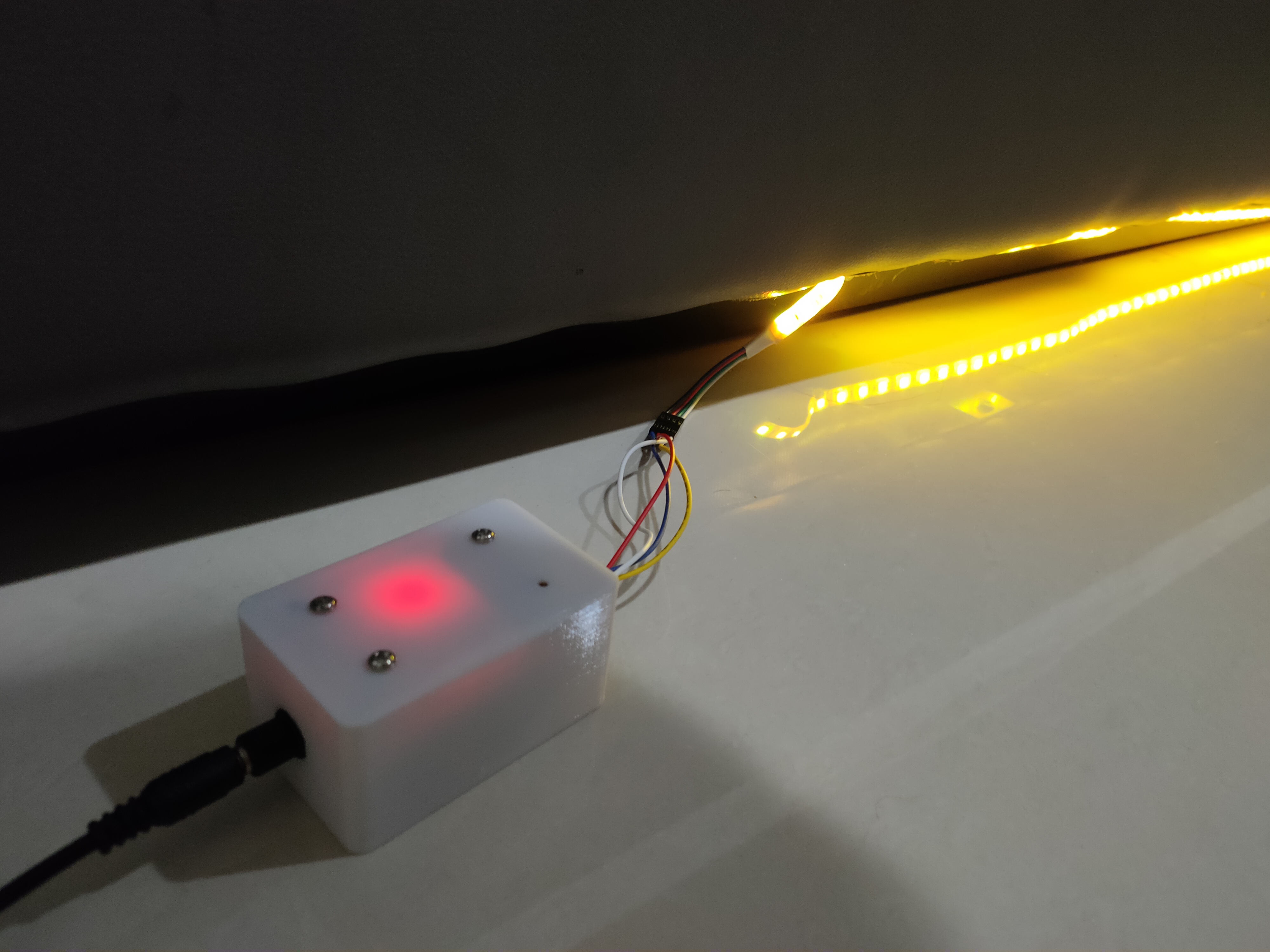
A small but significant update. I ordered a few photo resitors, aka LDR (Light Dependant Resistor) right after I finished writing MK1. It’s quite common for me to get ideas pop into my head as soon as I write things down.
Adding the LDR to the controller is a super easy task. I just modified the enclosure lid to have 2 tiny holes towards the edge, so it’ll pick up on the room light. The energy saving with this tiny sensor is significant. MK1 will automatically turn itself from 5pm to 11am, this will cut that on time by at least 50%.
Wire it to the ESP32 is also simple, just remember that we can’t use ADC1 when we need the WiFi. Any pins on ADC2 will work. On the code I also added more colours, so it’ll also lit up if I darken the room for nap time.
Sidebar: if you notice in the sketch, I also tried to use the mounting screw as capacitor button to turn all the LEDs into bright white (all 255s) to quickly brighten the room for a bit. But I'm having issues that it won't turn off consistently. I left the code in, I just don't wire the pins to the mounting screws.
Updated code and enclosure are at the same links: GitHub & Thingiverse.
About 5 years ago, I made this BLE coffee scale. It's hacked off of a scale I had. It was good enough to be used daily. The problem is that it's a bit tiring to have to use my phone as the screen, even though I have the calculator built into the app, sometimes I just want to pop open YouTube and watch something while brewing my coffee.
And here we are, a re-do of a project I did half a decade ago. The goal this time is:
Screen.
Speed / responsiveness.
Fit underneath my espresso machine.
2-3 kg capacity.
0.01g accuracy if possible.
App optional
As you can see from the pic on top, the prototype is pretty much ready. In reality, when brewing coffee, we don't need 0.1g accuracy. Definitely do not need 0.01g, but as a project goal, it's nice to aim high. The problem at this time is, the load cell I have lying around was the shitty one. Even worse than MK1's. It was just added to cart when I bought other things on Ali. It swings and wobbles at ±3g. Not practical as any kitchen scale, definitely not good enough for brewing coffee. I don't even know why they sell these. So what I did next was look for a good load cell. After I found it, I printed an adapter so I have a functioning place holder load cell as I design and print the enclosure. Pictured below. The load cells are ordered and on a slow boat from China. So, the expected project completion will be in 2-4 weeks.
1. Screen (and 6. App optional)
No 1 and 6 go hand in hand. But I don't plan on adapting this project with the previous app. I have other plans for the app side of things and it is very low on the totem pole atm. Screen just to address MK1 pain point. Also, as I mentioned in my Sous Vide post, it's a household device that only I can use. It is annoying.
Sidebar: I notice there were a surge of people making IOT window blinds. It has the same issues. No one else can open or close the blinds. If you want to make IOT devices, the app has to be optional.
2. Speed / responsiveness
Easy, dump HX711 and use ADS1232. This is the biggest hurdle of this project, there aren't many examples or tutorial that we can just simply follow to get numbers out of our load cell sensors. I plan on making a dedicated post for ADS1232. It is much much more responsive than HX711, and totally not as succeptible to noise compared to HX711.
3. Fit underneath my espresso machine.
Now that I have a 3D printer, I can print the enclosure in any shape I like. As you can see the picture, I made it "sideway". The screen is on the bottom right, because I'm left handed. I pour with the kettle on my left hand, so I still can clearly see the screen.
4 and 5. 2-3kg 0.01g accuracy
2-3 kg because my main brewing device is the 6-cup Chemex. The Chemex alone is 600ish grams. Most days, I brew 45g of coffee with 750g of water. That's almost 1.5kg total. 3kg limit gives be a bit of headroom, and I can still use it for baking or something.
0.01g are technically unrealistic unless I spent serious dollars on the load cells. Like getting a special order class C6 load cell. But that's entering the unlimited budget project territory. I'm not that crazy. In the end I ordred these load cells (Ali link: one and two). One is larger footprint but shorter, the other is smaller footprint but taller. Both are 3kg, both are class C3, and we'll see which of these fare better at 0.01g (or even at 0.1g) after they arrive.
This is not Project Libra I mentioned in the last post. It’s just a really simple project, I started and finish it in a day. Including the enclosure design and printing it.
A little background, a bit over a year ago I watched this youtube video and thought that it’s a good idea. I love having a night light that’ll lit up a room but not shining into your eyes during the night. However I have a low bed, no way I can put a PIR sensor all around without getting the wires become tripping hazard. So what I’ve done is just getting a cheap LED strip kit (with power supply and remote) and stick it around the bed.
Enters ESP32. I still can’t use a PIR sensor, but turning it on/off everyday becomes a chore. Often I’ve just left it on 24 hours. As you know, I’ve been playing with ESP a lot. Another great thing that ESP has is that it has RTC (Real Time Clock) built in. Along with WiFi, it check with current time with ntp server and will retain time accuracy even after power loss. Which is the example project called “Simple Time”.
This project, as you can see it’s just a remix of 2 guides. Simple Time and RGB LED Controller. All you need is an ESP32 Dev Board, and 3 N-channel MOSFET to run the LED. I just use the 30N06 that I already have plenty of. I added a sweet fade to the sketch so the LED won’t just snap into another color. Oh, and we’ll need a buck converter because the ESP can’t handle 12VDC input.
So, just load up the sketch. Plug everything together. Close the box. Plug everything in. And we’re done. This is one of those project that everything went smoothly. I only need to print the enclosure once. And the code just works. I added the fade later in the afternoon, and everything just went swimmingly.
Another idea I have was to check for sunset and sunrise time, but I opted against it. What I’d like to add in the future is a light sensor, so the LED strip will only light up when the room is dark.
The main difference of Katara compared to the predecessors is the use of a true water heating element (instead of a crockpot or rice cooker) and the water pump. It is a true immersion circulator. It can retain water temperature within 0.1ºC swing. It as 1500 Watt water heater, so 16 litre room temperature water can reach 60ºC within 15 mins or so. Anyway, Sous Vide is Sous Vide are so 5 years ago, but perfect steak, everytime. Let’s move on.
2. Over The Air (OTA) Update
My favourite feature, by far. Thanks to the AutoConnect library, this thing is amazing. There are many WiFi manager for the ESP32, but it’s the only one I’ve found that has the captive server out of the box.
Sidebar: if you don’t know what captive server is, it’s the pop-up you get when you joined a free wifi in airports or cafe.
It’s the most intuitive way. First you connect to the device’s WiFi, then it pop-up a thing so you can set it to connect to your home WiFi. You don’t need to memorise any IP address. The only downside, this and Blynk took like 70-something % of the ESP32 flash memory. That brings us to the next feature.
3. Blynk
Blynk is like an app (both iOS and Android) for your DIY IOT device for “free” and with minimal coding. You don’t need to roll your own API and server (in a way, I’ll get back to this later), and you most definitely do not need to code your own app. Blynk itself is quite confusing to use and a tad buggy, one thing in my code still causes a kernel panic. And you do BLYNK_WRITE() to read some values off of the app.
Blynk is “free”, upon registering, you get something like 2000 energy. And energy is their currency for buttons, LED, graphs, etc. If you need more, there’s IAP to get more energy. Unless, you roll your own blynk server, it’s dead simple. Just cut and paste a couple of things from the docs, I have mine run on my OctoPi.
And more importantly, I added a Blynk tab on AutoConnect with custom server support.
Final Thoughts
These are the major features that bring Katara works like a commercial product. Technically you can get everything from BOM. Follow the build guide. Figure out the water heater. Upload the released firmware as is. And it’ll work.
However, this is one of those projects you can’t cheap out on. It has been about a month long journey for me. Stressful but fun project I did in awhile. The final tally for the BOM is a bit under $60 (almost triple my original budget goal). Compared to an Anova (about $130) or a Joule (about $200), it’s a bit of money saving project. Especially over here, Anova is sold for almost $300 in local marketplace.
There are people who are selling these DIY Sous Vide “kit”, a death trap kit is what that is. If you were to build this, approach it with caution and respect. As with any other project that uses the AC line.
There we go, another CoronaCraft in the bag. Be safe, wear mask, and enjoy your steaks.


